


Arduino Pro Mini
This board was developed for applications and installations where space is premium and projects are made as permanent set ups. Small,? 5 V /16M version, powered by ATmega328
Safe shopping
Your data is always protected
Sale_coupon_15
235,00EGP
145 in stock
145 in stock
-
 Pick up from the Store
Everyday from 9 AM to 7 PM
-
 ARAMEX DELIVREY
2-3 Days
Total fees when checkout
-
Return within 14 days
Payment Methods:
Description
This board was developed for applications and installations where space is premium and projects are made as permanent set ups. Small,? 5 V /16M version, powered by ATmega328
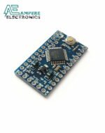
The Arduino Pro Mini is a microcontroller board based on the ATmega328P.
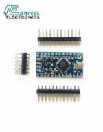
It has 14 digital input/output pins (of which 6 can be used as PWM outputs), 6 analog inputs, an on-board resonator, a reset button, and holes for mounting pin headers. A six pin header can be connected to an FTDI cable or Sparkfun breakout board to provide USB power and communication to the board. The Arduino Pro Mini is intended for semi-permanent installation in objects or exhibitions. The board comes without pre-mounted headers, allowing the use of various types of connectors or direct soldering of wires. The pin layout is compatible with the Arduino Mini.
There are two version of the Pro Mini. One runs at 3.3V and 8 MHz, the other at 5V and 16 MHz.
Arduino Pro Mini is open-source hardware! You can build your own board using the following files:
Power
The Arduino Pro Mini can be powered with an FTDI cable or breakout board connected to its six pin header, or with a regulated 3.3V or 5V supply (depending on the model) on the Vcc pin. There is a voltage regulator on board so it can accept voltage up to 12VDC. If you’re supplying unregulated power to the board, be sure to connect to the “RAW” pin on not VCC. The power pins are as follows:
RAW For supplying a raw voltage to the board. VCC The regulated 3.3 or 5 volt supply. GND Ground pins.
Memory
The ATmega328P has 32 kB of flash memory for storing code (of which 0.5kB is used for the bootloader). It has 2 kB of SRAM and 1kBs of EEPROM (which can be read and written with the EEPROM library.
Input and Output
Each of the 14 digital pins on the Pro Mini can be used as an input or output, using pinMode,digitalWrite, and digitalRead functions. They operate at 3.3 or 5 volts (depending on the model). Each pin can provide or receive a maximum of 40 mA and has an internal pull-up resistor (disconnected by default) of 20-50 kOhms. In addition, some pins have specialized functions:
- Serial: 0 (RX) and 1 (TX). Used to receive (RX) and transmit (TX) TTL serial data. These pins are connected to the TX-0 and RX-1 pins of the six pin header.
- External Interrupts: 2 and 3. These pins can be configured to trigger an interrupt on a low value, a rising or falling edge, or a change in value. See the attachInterrupt function for details.
- PWM: 3, 5, 6, 9, 10, and 11. Provide 8-bit PWM output with the analogWrite function.
- SPI: 10 (SS), 11 (MOSI), 12 (MISO), 13 (SCK). These pins support SPI communication, which, although provided by the underlying hardware, is not currently included in the Arduino language.
- LED: 13. There is a built-in LED connected to digital pin 13. When the pin is HIGH value, the LED is on, when the pin is LOW, it’s off.
The Pro Mini has 8 analog inputs, each of which provide 10 bits of resolution (i.e. 1024 different values). Four of them are on the headers on the edge of the board; two (inputs 4 and 5) on holes in the interior of the board. The analog inputs measure from ground to VCC. Additionally, some pins have specialized functionality:
- I2C: A4 (SDA) and A5 (SCL). Support I2C (TWI) communication using the Wire library.
There is another pin on the board:
- Reset. Bring this line LOW to reset the microcontroller. Typically used to add a reset button to shields which block the one on the board.
Relate Products:
Customer Reviews
Related Product s


Arduino MEGA 2560 CH340
1.199,00EGP